DESIGN
All roof cladding located at the join (except gutters), require a flashing fastened on both sides of the join.
Flashings near the edges of roofs or walls can be subjected to suction or negative wind loads that can be greater than
other positive imposed loads. Therefore the wind design load can be approach double that of the main roof area,
and as a result additional fixings are required to fasten flashings. The design wind load of each structure determines the
number and the spacing of flashing fasteners as well as locate wind zones on the building. A minimum number
of fixings are required to avoid flexing fatigue cracking of metal cladding under changing loads. This also prevents
noise or flapping. We recommends screws instead of rivets for fastening flashings. The larger diameter of a screw shaft gives a
greater shear capacity, and the larger head (or a washer) can be used to reduce the likelihood of pull out of the
fastener. The penetration of rain into the roof or wall through the flashings is largely caused by the air pressure differential
between the outside and inside of the roof or wall. Gusting wind can cause a significant pressure differential
which can fluctuate greatly. This in turn can cause a pumping action where water can be sucked into the join
which the flashing is protecting. Solutions to this problem include an anti-capillary offset
fold, a gap of up to 5mm, or a suitable sealant. All flashing edges require one of these measures to avoid capillary
action where flashings are subject to wind action when in contact with the roof or wall cladding.

Flashings, other than standard ridging, are produced to specific order and are designed and manufactured from
flat sheet or coil. If these flashings are required to match the colour of the profiled cladding sheets it is necessary for
the pre-painted flat sheet or coil to be made by the same manufacturer using the same process in order to avoid
differential colour matching or fading. Preferred maximum length of flashing is 6m, with
expansion joints provided after a maximum of two lengths of flashing (12m) have been fixed together, as any lap
secured by rivets or screws effectively becomes one length. Flashings are restricted in length in the same manner as are
roof and wall cladding sheets and are subject to the same requirements and expansion provisions.
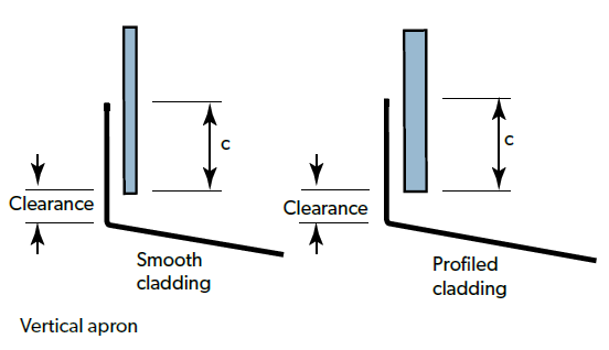
A minimum distance of 2-5mm from the edges of all flashings must be provided away from an adjacent
horizontal surface. This helps avoid the retention of moisture and deterioration at the cut edge of flashings.
When a cut edge is very close to some materials (concrete, plaster or some rubbers) this spacing is particularly
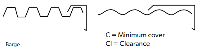
important. A minimum clearance (CL) of 25mm and a maximum clearance of 50mm should be provided at the end of wall
cladding. The cladding should not extend down to any apron flashing.